Once you have the plan setup as desired you can start populating it with the fixtures as required for the installation:
Pharos Designer incorporates a comprehensive fixture library grouped by manufacturer. A generic manufacturer is provided for standard fixtures such as dimmers, basic RGB LEDs and non-dim items that need to be switched such as fans or smoke machines.
A custom manufacturer is created when you make your own fixtures, either by right-clicking on a fixture within the library picker (not once placed on the plan) and selecting Customise Fixture to use this fixture as a starting point, or by pressing the Fixture Editor button at the top to create a fixture from scratch. Both operations will open the Fixture Editor.
Note however that common settings such as colour & gobo slots, size, shape and dimmer curve etc. can all be set on an individual fixture basis using the Fixture Configuration pane once the fixture has been deployed and selected, so creating a custom fixture library entry,a relatively complex process, may not be necessary.
The following icons are used to differentiate between fixture classes:

|
Moving light - wash |

|
DALI ballast (see DALI) |

|
Moving light - spot |

|
Conventional fixture |

|
Moving light - mirror |

|
Non-dim (switched control channel) or controller |

|
Accessory (eg. scroller) |

|
Media server |

|
Discrete LED fixture (to scale) |

|
Compound LED fixture (to scale) |

|
Fountain jet fixture | ||

|
4:3 PAL/NTSC AV device |

|
16:9 PAL/NTSC AV device |
The LED and compound LED fixture icons are drawn to scale (1cm:1pixel) so that, coupled with a correctly scaled background image, the resulting plan and simulation is as realistic as possible. The other icons are drawn to a standard size that, in most cases, will produce a realistic result. All placed fixture icons can however have their size (scale) and even shape modified using the Fixture Configuration pane.
When using the Simulator these icons instead render the fixture's output, even displaying the selected gobo and iris settings for moving lights. Fountain jets simulate differently however, extending in length to mimic the jet of water.
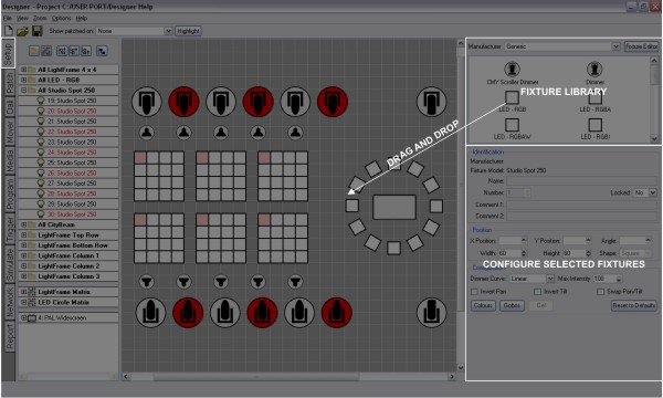
Simply chose a manufacturer, select the required fixture by clicking on it and then drag it onto its position on the plan, it will automatically be added to the Browser and grouped with all other fixtures of that type. Once placed, left click to select it, a red highlight will indicate the current selection, see selecting fixtures. Right click to delete, group or duplicate fixtures.
For rectangular arrays, positive width and height values will place the copies to the right and below respectively, negative to the left and above. Select either Rows or Columns to set the direction of the fixture numbering.
For circular arrays, select the radius, direction and count (number of fixtures) - complete circles are created in this way so, if arcs required, just delete those fixtures that are unwanted.
Note that pressing Ctrl after starting to drag will cause the selection to jump back to its original position and create a copy of the selection under the pointer.
Note that the fixture(s) will be completely removed from the project and all programming discarded.
NOTE: The appropriate Controller must be on the network and correctly associated to highlight fixtures. Fixtures can also be highlighted from the universe tab in Patch.
DALI fixtures/ballasts are dragged onto the plan in the same way as all other fixtures but they do not populate the Browser and no groups are automatically made since DALI fixtures are programmed and controlled via dedicated DALI Interfaces, see DALI.
Select "Generic Video" from the drop down of manufacturers. Choose the appropriate type of device (PAL or NTSC,16:9 or 4:3) and drag it onto the plan, just as you would for a lighting fixture.
However, unlike other fixtures, this will automatically add a project AVC to control that device, see Controller Association. Similarly duplicating or deleting these AV fixtures will automatically add or delete AVCs as required.
It is important to appreciate that AV fixtures are treated differently to lighting fixtures in that they are directly coupled to an AVC (which takes the same name) and thus require no patching. The AV fixture and its AVC should be thought of as a single, integrated entity. See Working with the Audio Visual Controller for information about programming AV fixtures and AVC playback.
You can use File > Import Fixture Plan to import a fixture layout from a CAD application via a CSV file, see fixture plan file format.
You can use File > Export Fixture Plan to export a fixture layout to a CAD application via a CSV file, see fixture plan file format. If you have any fixtures selected you will be prompted to export all or only those selected.
With a fixture selected the top two fields detail the fixture's manufacturer (manufacturer id) and model (model id), they are for reference only and can not be edited.
Here you can enter a new name for the fixture, useful to help make the browser easier to navigate, and the means to change the fixture's unique user number.
Every fixture added to the project is assigned a user number which is used as a shorthand method of selecting it, using the web interface's command line for example. Use the up and down arrows to change the number but note that only available numbers are shown so you may need to change the number of another fixture first to make that number available. Note that the user number does not affect the order of the fixtures in the Browser and thus the order used for transitions.
Select "Yes" to prevent the fixture(s) from being moved or included in drag selections. Evidently, once locked, drag selection is prohibited to select multiple fixtures to unlock so you must use the Browser instead.
Below this are two fields for entering any comments about the fixture, useful for annotating the project's documentation. These comments will appear in the fixture report and in exported CSV fixture plans.
Use these fields to set numerically the fixture's position and orientation on the plan and to change the size and shape of the fixture's icon, useful for tweaking their scale to that of the plan background if the default scale not used (1cm:1pixel).
It is desirable to position the fixtures on the plan as accurately as possible to improve both the accuracy of the programming (in particular pixel matrices created automatically from the plan layout) and the general neatness of the project and simulation.
Use the plan properties to set the spacing of the plan's grid, whether it is displayed and whether fixtures should snap to it. Holding Shift while dragging a fixture selection will invert the snap to grid behaviour.
Use the cursor keys to nudge a fixture selection up, down, left or right by the amount set as the grid spacing. Alternatively, use the up and down arrows by each of the fixture's position fields. Holding Shift while using the cursor keys performs a super-nudge of 10x the grid spacing.
Fixtures can be aligned to one another by making the selection and entering the value to be shared into the appropriate position field.
This pane allows you to configure the selected fixture(s):
The fixture's dimmer curve and maximum intensity can be set, use the Dimmer Curve pull-down to determine the type of cross fade the intensity channel will perform and set a Maximum Intensity level, useful for balancing light output.
DALI ballasts can be configured as allowed for by the DALI standard; Min Level (0>254), Max Level (0>254), Power On Level (1>254) and Bus Failure level (No change, 0>254). The standard specifies a level range of 0>254 with 255 being used as a special case meaning "no change", a mask if you like. Unlike DMX fixtures, these settings are stored in the ballasts themselves and so must be uploaded separately, see DALI.
Ballasts can also have their default Fade Time and Fade Rate set in the configuration pane.
Emergency DALI ballasts will also have the option to the set the Prolong time in the configuration pane. More information about emergency ballasts can be in the DALI topic.
NOTE: The default Fade Time and Fade Rate will be overwritten when new values are sent to ballasts during playback from triggers or programming. This is due to the way DALI ballasts store this information.
Moving lights can be customised for the project as one would on any sophisticated moving light console. Use Invert Pan, Invert Tilt and Swap Pan & Tilt to normalise the way they respond to the position controls.
Customise the fixture’s gobo & colour wheels by pressing the Gobos or Colours buttons to open the Configuration dialogs. Drag from the library onto the correct slots as required, press Ok to save or Cancel to abort.
For those working with gelled lights it is possible to simulate the gel’s colour so that the fixtures are rendered correctly, press the Gel button and select the required colour via the colour picker.
Use this to force the fixture to be redefined from its library definition, losing local changes and thus restoring it to its defaults. This is useful for updating fixtures on the plan with any library definition edits, forcing a redraw. Local changes to a fixture's geometry (shape, size) will be overwritten.
On the toolbar, use the Show patched on pull-down to select a Controller and then press Highlight to highlight the fixtures that are patched to that Controller. Select None instead of a Controller to highlight unpatched fixtures. Press Highlight again to turn it off.